Build Your Own Segmented Network
Segmenting devices on your network is a key step to securing your data and privacy. This will prevent big tech from scanning your network to identify nearby devices and contacts. They use this data for marketing purposes. For example, they may scan your network and identify a 3D printer. Now they can present you with ads relating to 3D printers. Or they can scan and see that you're alone with a college buddy watching sports. They can then start sending sports related adds to both of you. We recommend segmenting your network to prevent these types of scans. Also, if one of your devices gets hacked/compromised, then it will only have access to other devices on the same subnet. Your other subnets will be safe from the infected machine.
This guide will walk you through purchasing and configuring a small, segmented network suitable for a 2-3 person household. It will consist of 3 wired subnets (VLANs) and 3 wireless subnets (VLANs). You can tweak yours as best suits your needs by adding or subracting the number of VLANs you require.
We chose our equipment based on manufacturer reputability and ease of configuration. You could find less expensive options available. The firewall software we are using, PFSense, is open-souce and free for download. PFSense can be installed on most hardware, so long as it has multiple NICs. You should be able to repeat this setup with any VLAN capable switch and access point, though their configuration steps/commands will be much different than those in this guide. Just make sure that any switch and access point you purchase are 802.1q capable (VLAN capable).
Here are the subnets (VLANs) and their IP address ranges that we are using for this walk-through. You can tweak these settings to better suit your needs.
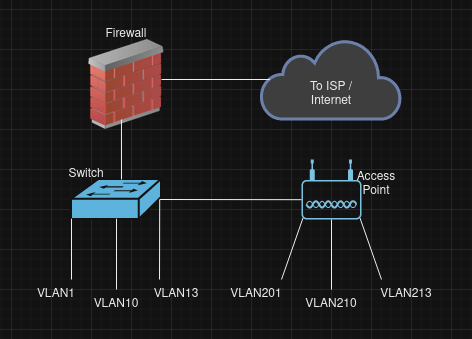

This image was generated on https://draw.io


Required Hardware / Software
Software Requirements:
Unifi Network Server Application (can be installed on Windows, Linux, MacOS)
https://help.ui.com/hc/en-us/articles/360012282453-Self-Hosting-a-UniFi-Network-Server
*NOTE: If you're not already familiar with Linux, then now would be an opportune time to get acquainted. Purchase an old laptop from a pawn shop for $150, and install Ubuntu 20.04.6 LTS (Focal Fossa) desktop image (free for download: https://www.releases.ubuntu.com/focal/ ). Once you have successfully installed 20.04.06 you should get a pop-up asking if you want to upgrade to 22.04. Answer "NO".
Once you have a laptop with Ubuntu 20.04.06, follow these 2 guides to install the Unifi Network Server Application:
- Youtube guide by the experts at Lawrence Systems: https://www.youtube.com/watch?v=lkUhWnDPutg
- Test that the Unifi App installs correctly by connecting to its web interface: https://127.0.0.1:8443 (127.0.0.1 tells the PC to connect to itself on port 8443)
Hardware Requirements:
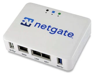
Firewall: Netgate 1100 - currently ~ $189

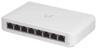
Switch: Unifi Lite 8 port POE switch - currently ~ $109
https://store.ui.com/us/en/pro/category/all-switching/products/usw-lite-8-poe

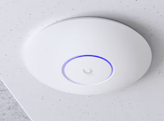
Access Point: Unifi U6-Pro - currently ~ $159
https://store.ui.com/us/en/pro/category/all-wifi/products/u6-pro
*NOTE: This AP is designed for ceiling mount. Unifi also has wall mountable AP's available if you find that preferable.

Firewall Setup
You should now have the required hardware, and you should also have a device/laptop with the Unifi Network Server Application installed. Once you have these in place, you can proceed with the rest of this guide.
Unpackage the equipment and connect it all together. We connected the equipment as follows:
Connect the 'WAN' port of the Netgate1100 to your ISP modem/ device
Conect the 'LAN' port of the Netgate1100 to 'port 8' on the Unifi LITE switch
Connect 'port 1' of the Unifi LITE switch to the access point
Connect your PC with Unifi Network Server installed to 'port 2' of the Unifi LITE switch
Power all the equipment on, and give them some time to boot up. Open a command prompt on the PC and type 'ip address'. You should have been assigned an IP address on the 192.168.1.x/24 network. If you didn't, then give the FW and switch more time to boot, and then reboot your PC, and check again.
Start by configuring the firewall. Open a web browser and connect to the following URL:
https://192.168.1.1
Login with the default creditials for PFSense (admin/pfsense).
After logging in, you should be presented with the following setup wizard:
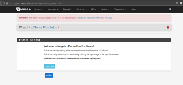

Click 'Next' to proceed through the initial setup Wizard.
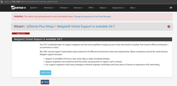
Click 'Next' on step 1 of the Wizard to continue:
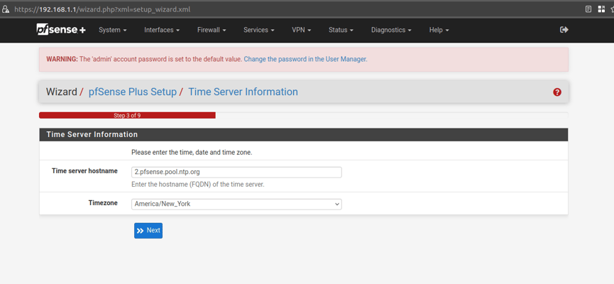
Wizard step 3.
leave time server at the default settings, and update to your correct timezone:

Wizard step 4.
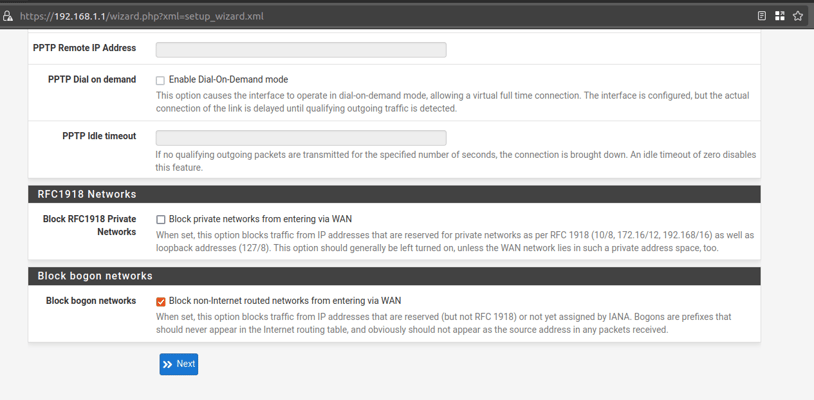
Leave all values at the default except for 'Block RFC1918 Private Networks'. There is a good chance that your ISP device will assign the firewall an IP address from the RFC1918 network ranges, so uncheck this box. If you find that your ISP doesn't assign an IP from RFC1918 ranges, then you can always come back later to re-check the box.

Wizard step 5.
Leave at the default settings:
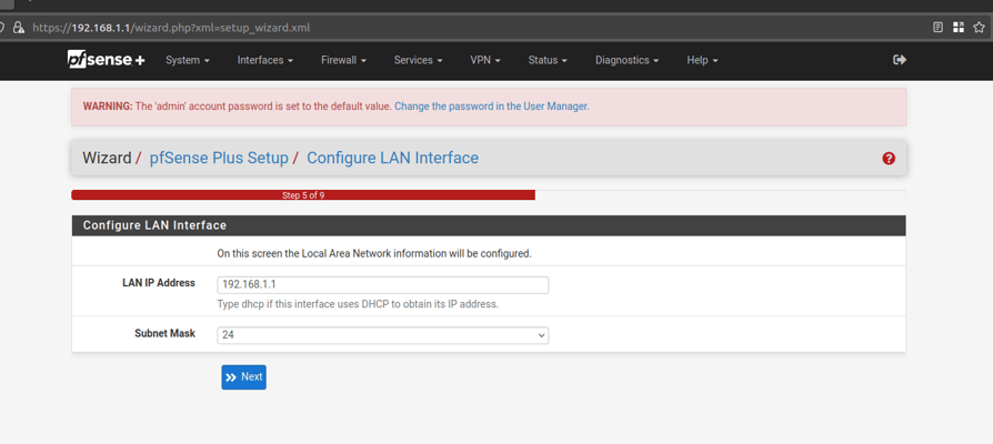

Wizard step 6.
Create a new password for the 'admin' user account.
Wizard step 7.
Click 'Reload':
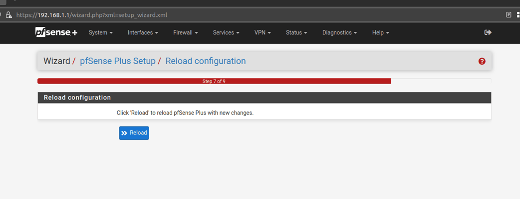

Wizard step 8.
Allow the FW to finish rebooting, and it should automatically proceed to step 9 when ready.
Wizard step 9.
Click on 'Finish'.
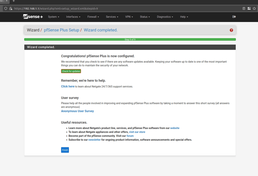

Click on 'OK' to accept any Welcome messages or terms of service.
This should bring you to the FW Dashboard. Check and confirm that your FW is running the latest version of OS. If it isn't, then go to System -> Update, and update your FW to the latest version:
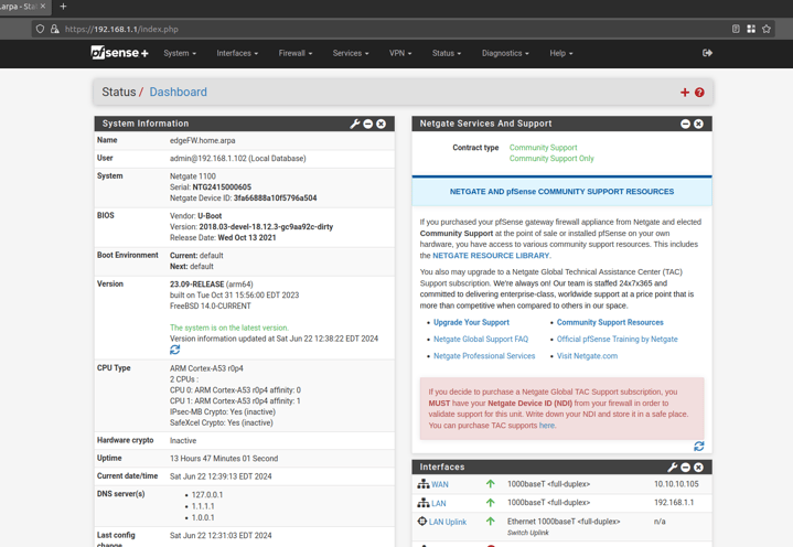

The Netgate 1100 ports share a backpane, so we will now need to add the new VLANs to the backpane. If you're using your own hardware with PFSense installed, then you may not need to make the below switch updates in PFSense.
In PFSense go to 'Interfaces -> Switches'.
Click on the 'VLANs' tab.
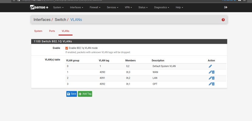
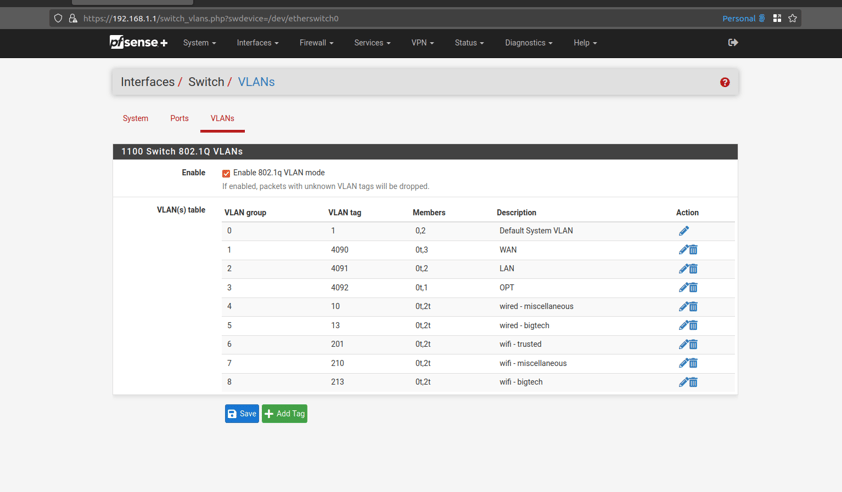
Your Netgate 1100 should have the following settings by default. Notice how the 'LAN' interface is members of '0' and '2':
The entry for VLAN 1 already exist. We will need to add the remaining VLANs (10, 13, 201, 210, 213).
Click on 'Add Tag'.
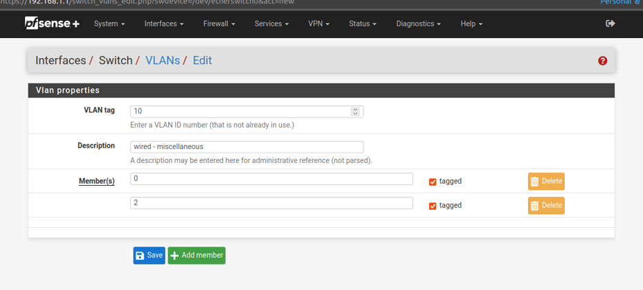
Enter the details for VLAN 10:
VLAN tag: 10
Description: wired - miscellaneous
Member(s): 0 , check the box for 'tagged'
Click 'Add Member' to add another member
Members(s): 2 , check the box for 'tagged'
Click 'Save':
Repeat the above for the remaining VLANs.
Click on 'Add Tag'
Enter the details for VLAN 13:
VLAN tag: 13
Description: wired - bigtech
Member(s): 0 , check the box for 'tagged'
Click 'Add Member' to add another member
Members(s): 2 , check the box for 'tagged'
Click 'Save':
Click on 'Add Tag'
Enter the details for VLAN 201:
VLAN tag: 201
Description: wifi - trusted
Member(s): 0 , check the box for 'tagged'
Click 'Add Member' to add another member
Members(s): 2 , check the box for 'tagged'
Click 'Save':
Click on 'Add Tag'
Enter the details for VLAN 210:
VLAN tag: 210
Description: wifi - miscellaneous
Member(s): 0 , check the box for 'tagged'
Click 'Add Member' to add another member
Members(s): 2 , check the box for 'tagged'
Click 'Save':
Click on 'Add Tag'
Enter the details for VLAN 213:
VLAN tag: 213
Description: wifi - bigtech
Member(s): 0 , check the box for 'tagged'
Click 'Add Member' to add another member
Members(s): 2 , check the box for 'tagged'
Click 'Save':
You should now have all of the VLANs configured on the switch, and they should look like the following:

Wizard Step 2.
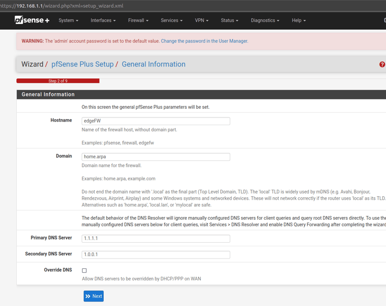
Give the firewall a hostname, DNS servers, and uncheck the box for 'Override DNS':
Example settings:
Hostname: edgeFW
Domain: can be left blank unless you're using local hostnames/DNS
Primary DNS Server: 1.1.1.1
Secondary DNS Server: 1.0.0.1





Repeat the above step for the remaining VLANs.
Create an entry for VLAN 13.
Click on 'Add' to create a new VLAN.
Parent Interface: mvneta0 (this should match the existing VLANs from above picture)
VLAN Tag: 13
VLAN Priority: 0
Description: wired - bigtech
Click 'Save'
Create an entry for VLAN 201.
Click on 'Add' to create a new VLAN.
Parent Interface: mvneta0 (this should match the existing VLANs from above picture)
VLAN Tag: 201
VLAN Priority: 0
Description: wifi - trusted
Click 'Save'
Create an entry for VLAN 210.
Click on 'Add' to create a new VLAN.
Parent Interface: mvneta0 (this should match the existing VLANs from above picture)
VLAN Tag: 210
VLAN Priority: 0
Description: wifi - miscellaneous
Click 'Save'
Create an entry for VLAN 213.
Click on 'Add' to create a new VLAN.
Parent Interface: mvneta0 (this should match the existing VLANs from above picture)
VLAN Tag: 213
VLAN Priority: 0
Description: wifi - bigtech
Click 'Save'
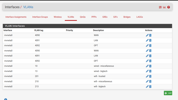
The remaing VLANs should now be added, and look like the following.
*NOTE: We do not need to create an entry for VLAN 1, because it is the default VLAN and is already assigned to the 'LAN' interface:
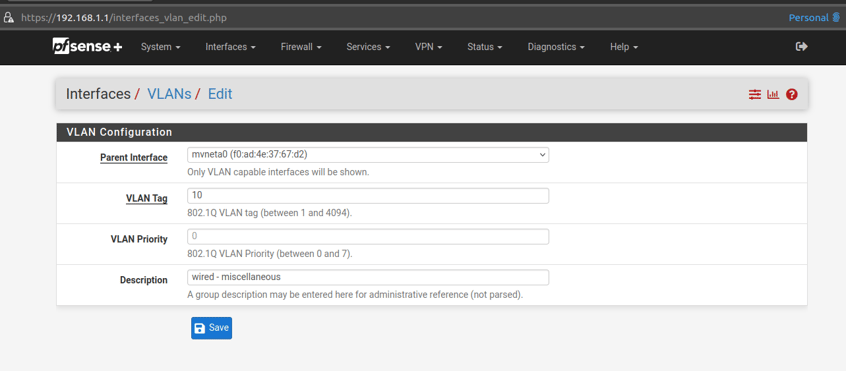
Create an entry for VLAN 10.
Parent Interface: mvneta0 (this should match the existing VLANs from above picture)
VLAN Tag: 10
VLAN Priority: 0
Description: wired - miscellaneous
Click 'Save':
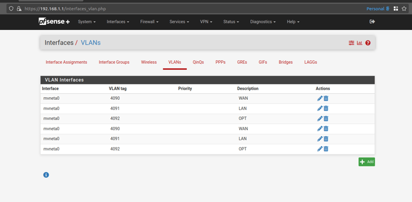

Above we added the VLANs to the PFsense switch (layer 2 of OSI model). Now we need to create IP interfaces for the VLANs (layer 3 of OSI model).
Go to 'Interfaces -> Assignments' , and then click on the 'VLANs' tab.
Click on 'Add' to create a new VLAN.




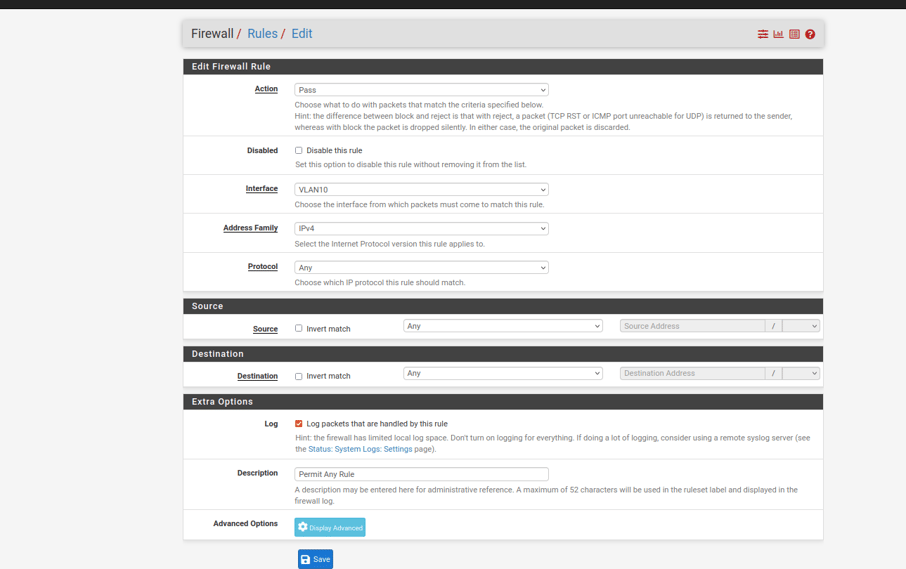
Click 'Add' to create another rule for VLAN10. This will be the permit any rule.
*NOTE - Order does matter. The firewall rules are applied in a top down order. Make sure that the deny rules are above the permit any rule.
Configure the permit any rule as follows:
Action: Pass
Address Family: IPv4
Protocol: Any
Source: Any
Destination: Any
Log: Yes
Description: Permit Any Rule
'Save' and then 'Apply'
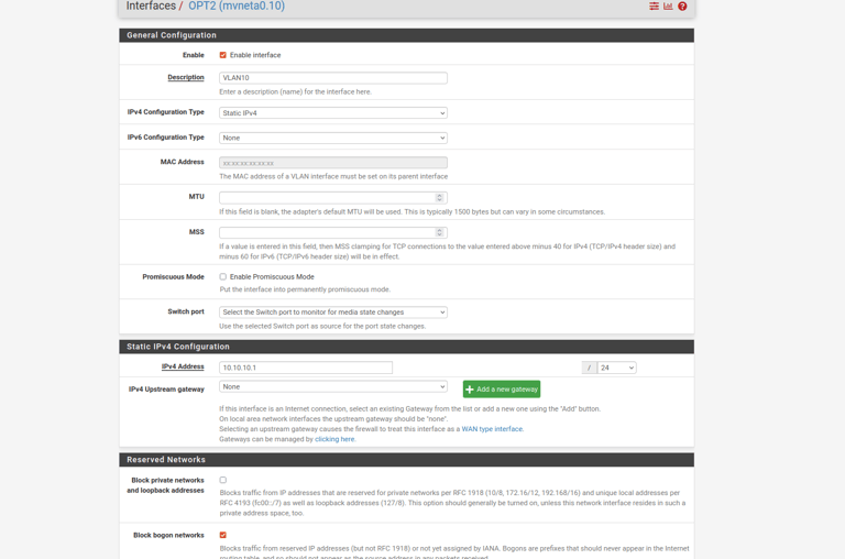
Configure the VLAN 10 interface with the following settings:
Enable: Yes , check the box next to 'Enable interface'
Description: VLAN10
IPv4 Configuration Type: Static IPv4
IPv4 Address: 10.10.10.1/24 (make sure to update the mask to /24)
Check the box to 'Block bogon networks'
Leave all other fields at their default
'Save' and then 'Apply' the changes
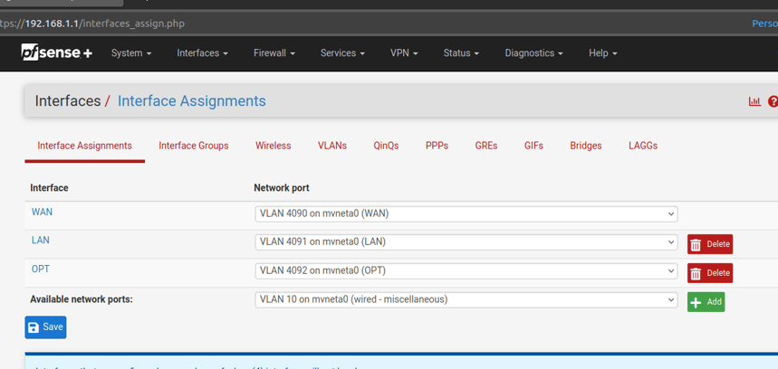
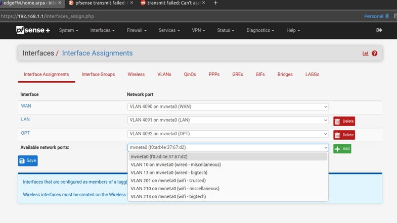
Select 'VLAN 10' and click 'Add'.
Next we need to enable the interfaces and configure them with their IP addresses.
Go to 'Interfaces -> Assignments'
You should see the new VLAN interfaces available to be added; as below:
Click on the newly created interface to configure it:
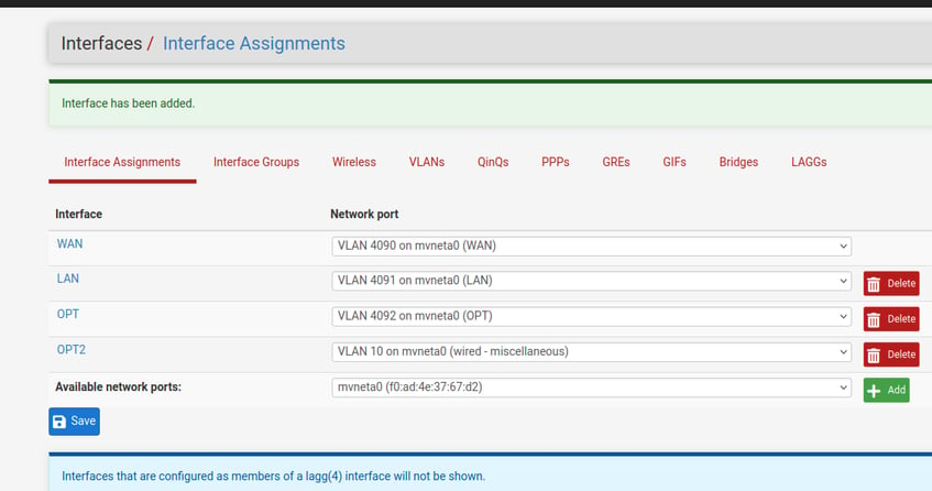

Repeat the above steps for the remaining VLAN interfaces.
Add each VLAN as a new interface on the 'Interfaces -> Assignments' page.
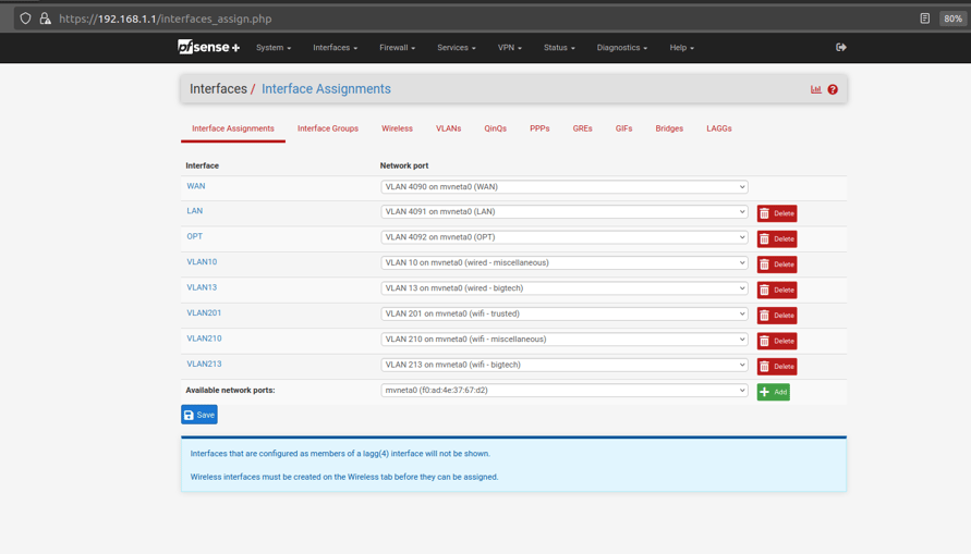
It should look similar to the following once all of your VLANs have been added as interfaces:
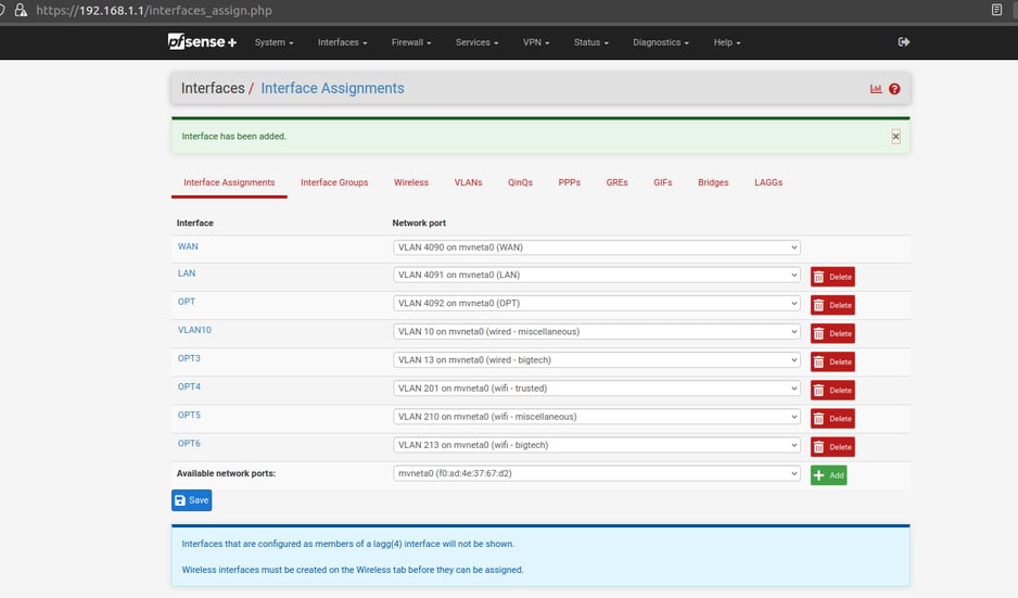

Now edit the newly added interfaces as follows:
Edit the interface for VLAN 13 as follows:
Enable: Yes , check the box next to 'Enable interface'
Description: VLAN13
IPv4 Configuration Type: Static IPv4
IPv4 Address: 10.13.13.1/24 (make sure to update the mask to /24)
Check the box to 'Block bogon networks'
Leave all other fields at their default
'Save' and then 'Apply' the changes
Edit the interface for VLAN 201 as follows:
Enable: Yes , check the box next to 'Enable interface'
Description: VLAN201
IPv4 Configuration Type: Static IPv4
IPv4 Address: 192.168.201.1/24 (make sure to update the mask to /24)
Check the box to 'Block bogon networks'
Leave all other fields at their default
'Save' and then 'Apply' the changes
Edit the interface for VLAN 210 as follows:
Enable: Yes , check the box next to 'Enable interface'
Description: VLAN210
IPv4 Configuration Type: Static IPv4
IPv4 Address: 10.210.210.1/24 (make sure to update the mask to /24)
Check the box to 'Block bogon networks'
Leave all other fields at their default
'Save' and then 'Apply' the changes
Edit the interface for VLAN 213 as follows:
Enable: Yes , check the box next to 'Enable interface'
Description: VLAN213
IPv4 Configuration Type: Static IPv4
IPv4 Address: 10.213.213.1/24 (make sure to update the mask to /24)
Check the box to 'Block bogon networks'
Leave all other fields at their default
'Save' and then 'Apply' the changes
All of your VLANs should now have enabled interfaces with IP addresses/subnets assigned.
Next, you will need to configure DHCP settings for each subnet. This will allow your networked devices to connect automatically upon boot.
Go to 'Services -> DHCP Server'
You should see all 6 of the subnets listed (LAN is our VLAN1 subnet)
Start by updating 'LAN' with the following settings:
Address Pool Range: 192.168.1.200 -TO- 192.168.1.250
DNS Servers: 1.1.1.1 , 1.0.0.1
Leave all other fields as they are
'Save' and then 'Apply'

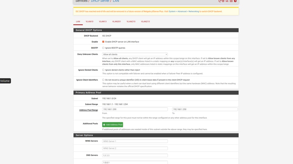

Now update the remaining subnets with the following settings
Go to 'Services -> DHCP Server'
Update 'VLAN10' with the following settings:
Enable: Yes (Check the box next to 'Enable')
Address Pool Range: 10.10.10.200 -TO- 10.10.10.250
DNS Servers: 1.1.1.1 , 1.0.0.1
Leave all other fields as they are
'Save' and then 'Apply'
Update 'VLAN13' with the following settings:
Enable: Yes (Check the box next to 'Enable')
Address Pool Range: 10.13.13.200 -TO- 10.13.13.250
DNS Servers: 1.1.1.1 , 1.0.0.1
Leave all other fields as they are
'Save' and then 'Apply'
Update 'VLAN201' with the following settings:
Enable: Yes (Check the box next to 'Enable')
Address Pool Range: 192.168.201.200 -TO- 192.168.201.250
DNS Servers: 1.1.1.1 , 1.0.0.1
Leave all other fields as they are
'Save' and then 'Apply'
Update 'VLAN210' with the following settings:
Enable: Yes (Check the box next to 'Enable')
Address Pool Range: 10.210.210.200 -TO- 10.210.210.250
DNS Servers: 1.1.1.1 , 1.0.0.1
Leave all other fields as they are
'Save' and then 'Apply'
Update 'VLAN213' with the following settings:
Enable: Yes (Check the box next to 'Enable')
Address Pool Range: 10.213.213.200 -TO- 10.213.213.250
DNS Servers: 1.1.1.1 , 1.0.0.1
Leave all other fields as they are
'Save' and then 'Apply'
DHCP should now be enabled for each subnet. The subnets should assign IP addresses ending in 200-250, and they should assign 1.1.1.1 and 1.0.0.1 as DNS servers.
Finally, you're ready to configure the firewall rules. To keeps things simple, we recommend only 2 rules for this setup. The first rule is to block traffic between one subnet to another. The second rule will allow everything else.
Start by going to 'Firewall -> Aliases'
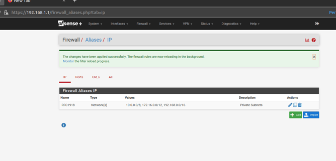
Click 'Add' to create a new IP Alias
Configure the Alias with the following settings:
Name: RFC1918
Description: Private Subnet Ranges
Type: Network(s)
Network or FQDN: 10.0.0.0/8
Network or FQDN: 172.16.0.0/12
Network or FQDN: 192.168.0.0/16
'Save' and then 'Apply'
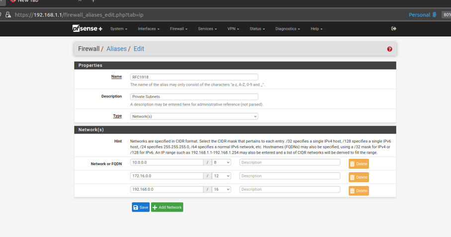

You should now have the following Alias:

Go to 'Firewall -> Rules'
Click on 'VLAN10' and then click 'Add'
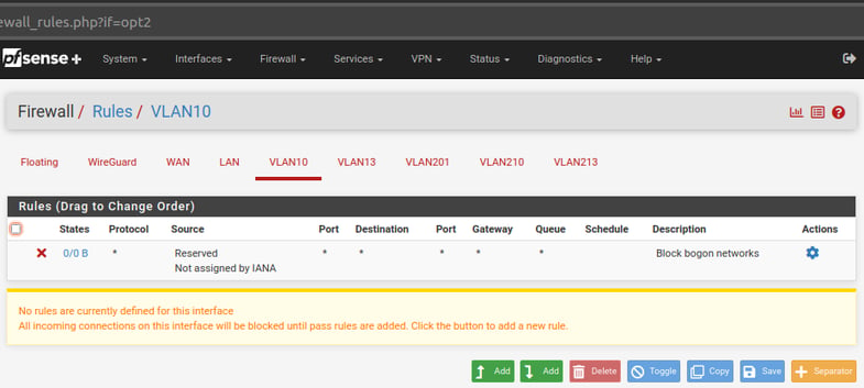

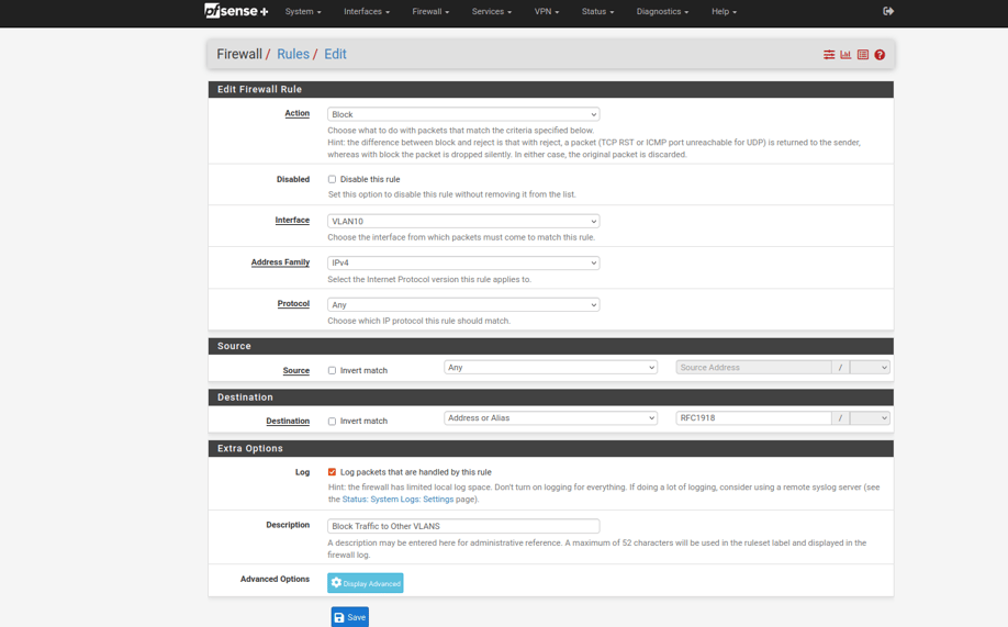
Configure the Rule with the following settings:
Action: Block
Address Family: IPv4
Protocol: Any
Source: Any
Destination: Address or Alias - type in alias name 'RFC1918'
Log: Yes
Description: Block Traffic to Other VLANs
'Save' and then 'Apply'


Your VLAN10 interface should now have the following firewall rules:
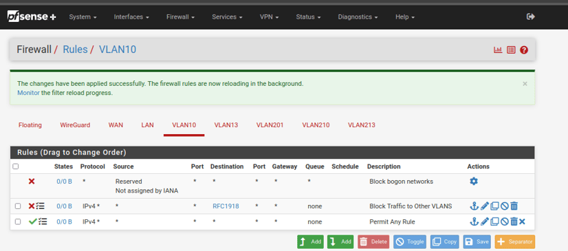

Repeat the above steps for the remaing VLANs (13, 201, 210, 213).
All of the new VLAN interfaces should now have 3 rules. The 'Block bogon' rule, the 'RFC1918' rule, and the 'Permit Any' rule. You can add an 'RFC1918' rule to the 'LAN' interface if you want. Just be sure to add it above the existing permit any rule.
Switch and AP Setup
Open the Unifi Network Server Application by connecting to the following URL:
https://127.0.0.1:8443
*NOTE: IP 127.0.0.1 is the 'local host' address. It basically tells the PC to connect to itself on port 8443
You should see the following page. Rename your server if you wish, select your appropriate country, and agree to the 'Terms of Service':
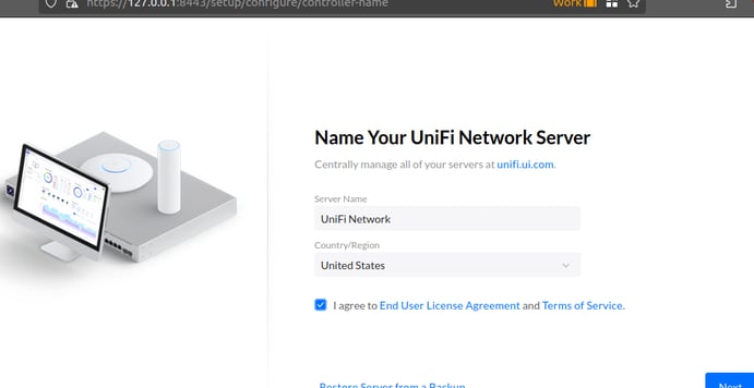

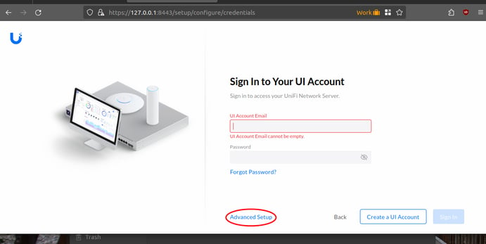
On the next page you are asked to sign into your UI cloud account. DO NOT create a UI cloud account.
Instead, click on 'Advanced Setup', and click 'Skip' when prompted to create a UI account:
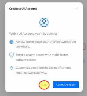

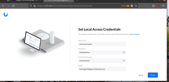
Set your username and password for local management (not stored in the cloud). It forces you to provide an email address. If you don't wish to give them your personal email, then you can use a disposable email from Guerrilla Mail (https://www.guerrillamail.com/).
Click 'Finish':
You should now be at the Unifi Network dashboard, and there should be no active clients or devices. On the left column, there should be 1 alert for 'System Logs'.
Click on 'System Logs' to view the alert:
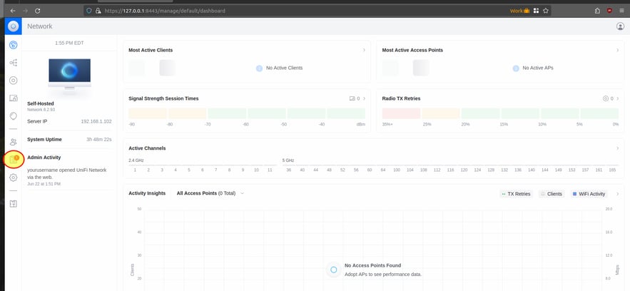

The alert should inform you that there are devices ready for adoption.
Click on the link to 'Adopt all'.
This should bring up the below page showing the 2 Unifi devices (switch and AP) that are ready for adoption.
Click on 'Adopt all' at the top of the page to adopt both of the devices:
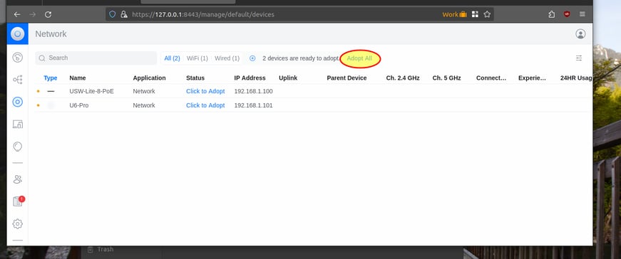

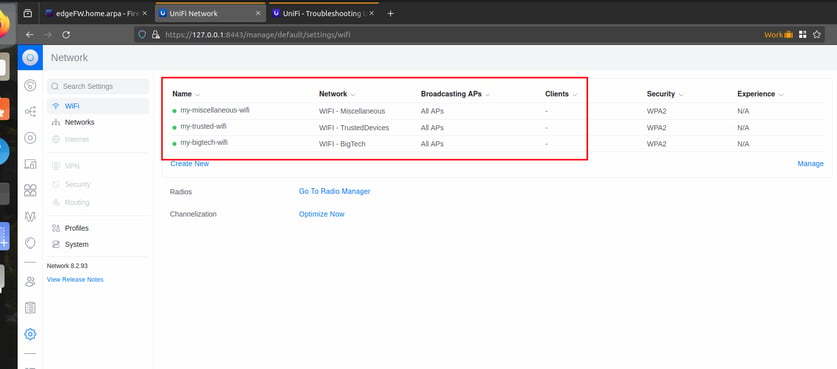
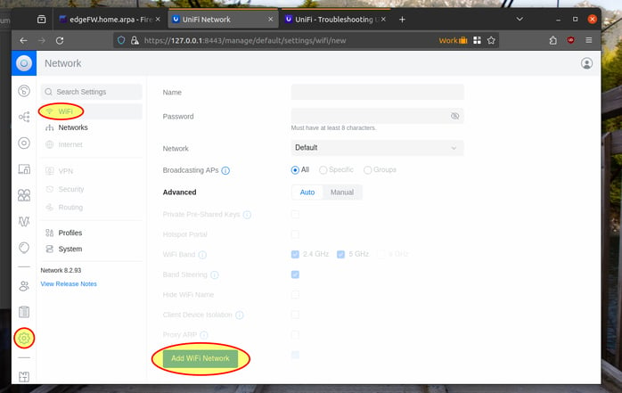
Now click on 'Settings -> WiFi' so that we can create our 3 WIFI SSIDs, and associate them with the appropriate VLAN we created above.
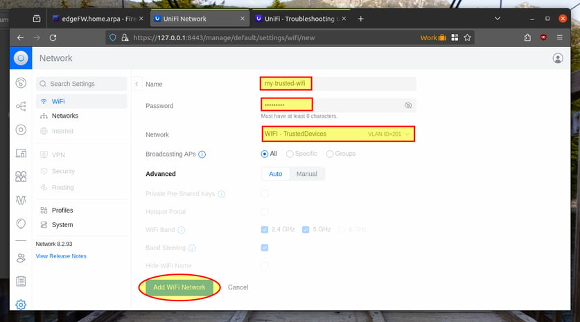
Click on 'Add WiFi Network':
Create an SSID for trust WIFI (VLAN 201).
Name: my-trusted-wifi
Password: Configure a strong password
Network: Select 'VLAN ID = 201' from the drop-down.
Leave all other options at the default.
Click 'Add WiFi Network':

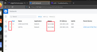
You can monitor the progress by watching the 'Status' column. Once fully adopted there should be a green dot next to the devices, and their status should say 'Up to date':
Now that the switch and AP are imported into the Unifi Network Manager, we can proceed with configuring them.
Start by configuring the VLANs.
Click 'Settings' in the left column, and then click on 'Networks'. Then click on 'New Virtual Network':
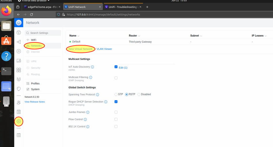

VLAN 1 already exist as the 'Default' network.
Add the details for our next wired VLAN (vlan 10).
Network Name: Wired - Miscellaneous
VLAN ID: 10
Click 'Add' at the bottom of the screen:
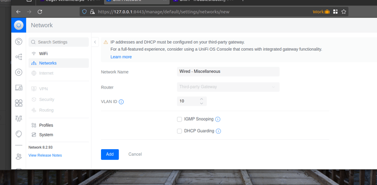

Click on 'New Virtual Network', and repeat the above steps to add your remaining VLANs:
(details for VLAN 13)
Network Name: Wired - BigTech
VLAN ID: 13
Click 'Add' at the bottom of the screen, then click 'New Virtual Network' to add the next VLAN.
(details for VLAN 201)
Network Name: WIFI - TrustedDevices
VLAN ID: 201
Click 'Add' at the bottom of the screen, then click 'New Virtual Network' to add the next VLAN.
(details for VLAN 210)
Network Name: WIFI - Miscellaneous
VLAN ID: 210
Click 'Add' at the bottom of the screen, then click 'New Virtual Network' to add the next VLAN.
(details for VLAN 213)
Network Name: WIFI - BigTech
VLAN ID: 213
Click 'Add' at the bottom of the screen.
You should now have all the VLANs added to the Unifi configuration, and they should look similar to the following:
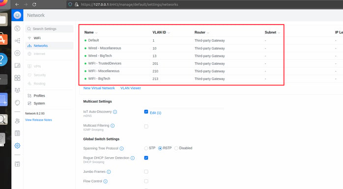

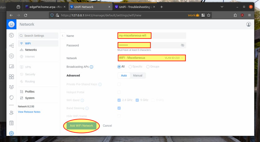
Click 'Create New' to create our next WIFI SSID for Miscellaneous (VLAN 210).
Name: my-miscellaneous-wifi
Password: Configure a strong password
Network: Select 'VLAN ID = 210' from the drop-down.
Leave all other options at the default.
Click 'Add WiFi Network':
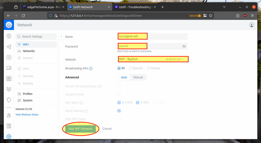
Click 'Create New' to create our final WIFI SSID for BigTech devices (VLAN 213).
Name: my-bigtech-wifi
Password: Configure a strong password
Network: Select 'VLAN ID = 213' from the drop-down.
Leave all other options at the default.
Click 'Add WiFi Network':






This will bring you to the port manager page that looks like the following:
Finally, we need to configure the switchports. The ports are setup to allow all VLANs by default. We want to modify this so that the ports only allow the VLANs we want them to.
Click on 'Unifi Devices' in the left menu bar, and then click on the switch.
Now click on 'Port Manager':
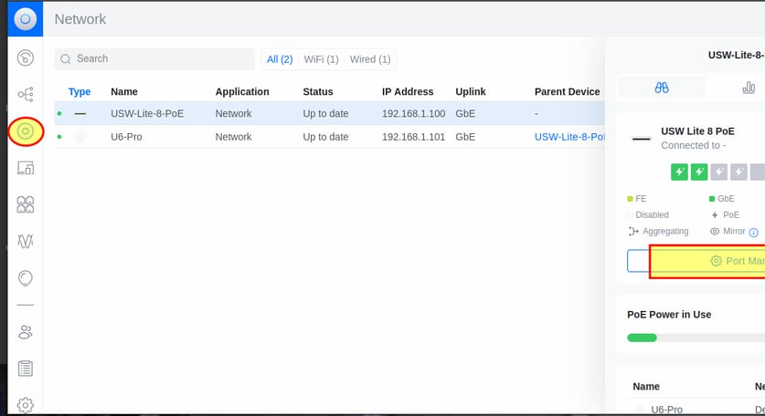

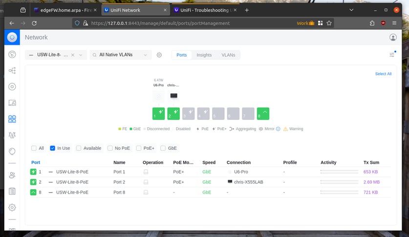

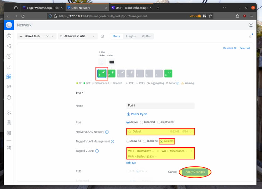
Click on port 1 (connection to the Access Point).
Leave the Native VLAN as default (VLAN 1)
Click 'Custom' next to 'Tagged VLAN Management', and then select our WIFI VLANs to be tagged (VLANs 201, 210, and 213)
Leave the other options at the default and click 'Apply Changes'.

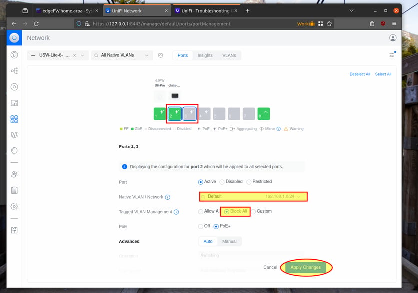
Click on ports 2 and 3. This will allow you to update both of them at the same time. We configured ours for VLAN 1 only. You can modify these switchport settings to better suit your needs.
Leave the 'Native VLAN' as Default (VLAN 1)
Tagged VLAN Management: Block All
Leave other options at the default value and click 'Apply Changes':

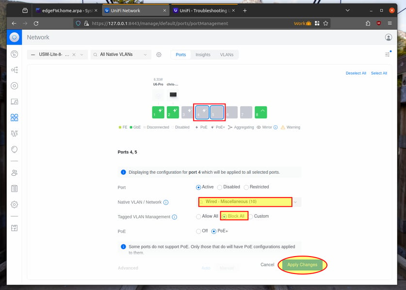
Click on ports 4 and 5. This will allow you to update both of them at the same time. We configured ours for VLAN 10 only. You can modify these switchport settings to better suit your needs.
Change the 'Native VLAN' to Wired - Miscellaneous (VLAN 10)
Tagged VLAN Management: Block All
Leave other options at the default value and click 'Apply Changes':

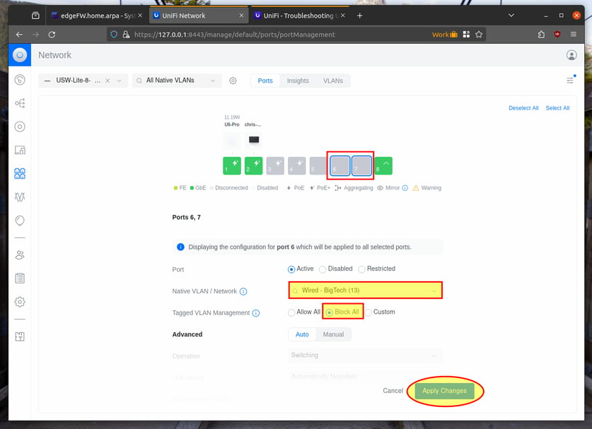
Finally, click on ports 6 and 7. This will allow you to update both of them at the same time. We configured ours for VLAN 13 only. You can modify these switchport settings to better suit your needs.
Change the 'Native VLAN' to Wired - BigTech (VLAN 13)
Tagged VLAN Management: Block All
Leave other options at the default value and click 'Apply Changes':

That concludes the Unifi device setup. You should now see the 3 WIFI networks when you check for available wireless networks. You should be able to connect to each of them, and each one should give you a different IP subnet.
We also hardcoded the remaining switchports. If you connect to ports 2-3 you should get an IP from VLAN 1.
If you connect to ports 4-5, you should get an IP from VLAN 10.
And if you connect to ports 6-7, you should get an IP from BigTech VLAN 13.
You should now have all 3 SSID's created, and associated to the proper VLAN/Network:
